
Faults form within the Earth’s brittle crust and, the largest of them, are capable of generating M > 6 earthquakes, with the seismic energy released causing ground shaking over distances up to hundreds of kilometres from their epicentre. Fault-surfaces are commonly buried beneath the ground surface and are generally visible only in outcrops (i.e.24), and/or through the use of geophysical tools25. Fault ruptures during large-magnitude (>M6) earthquakes often, however, propagate to the ground-surface and displace topography (e.g. fan surfaces, spurs, ridge-crests and streams), with displacements ranging from a few cm’s to several metres (i.e.26,27,28). It is these fault traces that comprise the core of the AFG in onshore Greece.
In the following, we first present our methodological approach to mapping individual fault-traces using a number of specific geomorphic criteria (see ‘Fault trace mapping’ section) and subsequently discuss the individual steps taken to characterise and attribute each AFG trace. Collectively, the AFG contains 3815 normal, reverse and strike-slip fault traces (see ‘Classification of fault type’), with each trace represented on the landscape as earthquake fault-scarp, topographic fault-scarp or flexure (Fig. 1). Fault traces are subsequently merged into individual faults and, where possible, fault systems (see section ‘Fault Hierarchy: from fault traces, to faults and fault systems’) (Fig. 2a,b). By tailoring the definition of active faulting for Greece (see discussion below), fault traces are subsequently classified as historically active, active, probably active or of uncertain activity. Last, following specific geomorphic criteria, active fault traces are classified as sharp, moderate, rounded or poor (see section ‘A geomorphic classification in AFG’). The flow-chart in Fig. 2a summarizes the methodology developed in AFG and discussed in detail below.
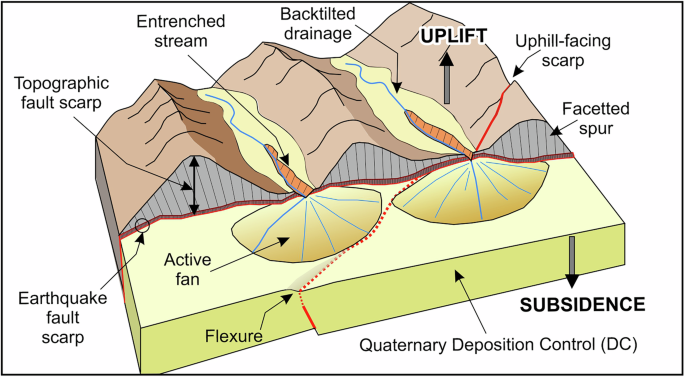
Summary of landscape features used in AFG. Schematic diagram illustrating the main geomorphic features used to trace the surface expression of active faults in AFG (such as earthquake fault-scarps, topographic fault-scarps, uphill-facing scarps, flexures, etc) atop a schematic Quaternary depocenter (DC).
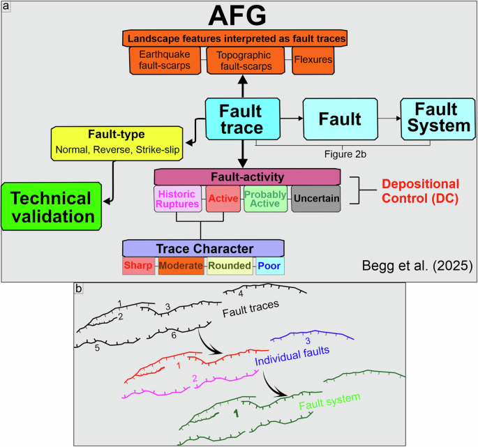
(a) Flow chart summarizing the AFG structure. (b) diagram illustrating schematically the upscaling in AFG from individual fault traces to faults and, where applicable, fault systems.
Fault trace mapping
The AFG is of Greek national onshore coverage and has been compiled at 1:25,000 scale. Because it is geomorphologically-based, it is restricted to fault traces with surface expression (with the single exception of a concealed fault that ruptured historically and was identified through its aftershock sequence10,29). Linear landscape features such as ridge-crest damage, ridge-crest displacement, valley alignment, air-gaps along ridgelines, or drainage displacements were used as proxy indicators for faulting30. Initial systematic geomorphological scans of DEMs, hillshades and slope-maps allowed identification of lineaments that warrant further investigation. To assess the tectonic origin of these lineaments we tested them against the following geomorphic criteria, with the requirement that at least one is honoured (Fig. 1a):
-
a)
Measurable displacement of materials traversed by traces or lineaments.
-
b)
Prescence of fault facets or facetted spurs.
-
c)
Stream-channel displacement or changes in channel-incision across the inferred trace.
-
d)
Linear range fronts adjacent to areas of active deposition.
-
e)
Elongate slope changes that cut geomorphic features and cross geological units.
-
f)
Elongate lineaments clearly distinct from basement texture and/or cross-cutting bedrock fabric.
-
g)
Significant displacement or truncation of ridge-lines.
Here, the term displacement refers to any type of displacement (vertical, horizontal, or oblique), and the above criteria apply to dip-slip (normal or reverse), strike-slip (left or right-lateral) and/or oblique-slip faults. Following verification that these features represented fault traces, digitisation and attribution of geometric fields (dip direction and orientation) followed. All assembly and processing of data included in AFG were completed using the open-access software QGIS31. Tiles of 2 m digital elevation models (DEMs) from the Greek Cadastre Agency were merged prior to fault mapping, and hillshades from varying azimuths of illumination and inclination angles were generated and used as overlays on colour-ramped DEMs. Derivative slopemaps were also used as overlays and proved particularly useful in identifying low, linear traces across gently sloping landscapes (e.g. Figure 3). Existing published literature describing and mapping active faults in Greece was assembled and all relevant maps were georeferenced. Each fault was checked against published georeferenced maps to determine whether it had previously been identified. Where previously identified (even approximately), appropriate citation was included. Thus, an empty shapefile, with a coordinate reference system of WGS 84 (EPSG:4326), was progressively populated with digitised and attributed lines during a complete and systematic scanning of the entire country. Google Earth was used, where possible, to corroborate the presence of faults using satellite imagery.
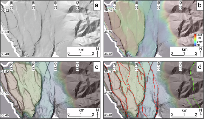
Enhanced fault mapping through digital elevation raster images. Figure demonstrating the methodology followed to map fault traces using digital elevation models and various derivative raster images. Here, an area immediately NW of Gerolimenas in south Peloponnese is (a) lit from 315° at 40°; (b) illustrated with slightly transparent hillshade (70% transparency) underlain by the colour-ramped DEM; (c) is shown as colour ramped DEM and hillshade overlain by slightly transparent (70%) slopemap; and (d) populated by fault traces mapped using collectively the above data.
It should be noted that there are several places where fault traces are discontinuous in geomorphic expression over distances of a kilometre or more (i.e. where Holocene deposition obscures pre-existing scarps) and thus the trace cannot be mapped at 1:25,000 scale within these intervals. In these cases, fault-traces are located as accurately as possible within the context of the landscape between mappable traces. Further, where lineaments are parallel to bedrock fabric, including bedding, they have commonly not been interpreted as fault traces in AFG. Last, short traces (length <100 m) with little or no displacement, particularly when extending proximal to other larger features (i.e. fault-splays at tips or fault junctions), have not been mapped exhaustively. Thus, while the suite of AFG traces identified from the DEMs is not exhaustive, those present are believed to represent all major faults and fault systems in onshore Greece that outcrop at the ground surface.
Classification of fault type
Observed displacements of landscape features underpinned assignation of a ‘fault type’ for each AFG trace (normal, reverse or strike-slip). Dip-slip on landscape features can be readily observed where fault scarps are formed and record vertical displacement. Almost all traces in AFG are attributed to being elements of normal faults or fault systems (Table 1). Assessing whether there has been oblique or strike-slip movement on a fault is more difficult and requires careful examination of the landscape to identify lateral displacements of unambiguous piercing points (e.g., ridge-crests and spurs, or streams). For a fault with long-term downthrow on the hanging-wall resulting in active deposition, strike-slip displacement may be difficult to observe in the landscape. However, laterally offset fans and stream courses should demonstrate strike-slip displacement. Despite careful examination for indicators of significant lateral displacements, only 20 strike-slip traces were recorded (Table 1), suggesting that strike-slip displacement is unlikely to be an important deformation mechanism at the ground surface in onshore Greece.
Earthquake fault-scarps, topographic fault-scarps and flexures
The 3815 AFG traces mapped using the DEMs include earthquake fault-scarps, topographic fault-scarps and flexures (Fig. 1a). Fault-scarps represent surface displacements along active faults produced either by single surface-rupturing earthquakes (co-seismic fault scarp) or, more commonly, due to several (<10) large-magnitude earthquakes on individual faults32,33. Earthquake fault-scarps are sharp and often linear or gently curved discontinuities commonly of <20 m height. In limestone bedrock these scarps are defined by the outcropping fault surfaces, which typically dip at 60–70°. Fault-scarps due to historic surface-rupturing earthquakes in Greece range in dip-slip from 10 cm to 4 m (i.e.34,35,36). In contrast, topographic fault-scarps are larger topographic lineaments that represent 100 m to kilometer-scale displacements accrued on faults over 100’s of thousand to millions of years due to many (10s to 1000s) large-magnitude earthquakes32,37 (Fig. 1a). Flexures recorded from the DEMs may also result from a series of rupture events that, in this case, failed to penetrate to the ground surface (Fig. 1a). Here, the location of the buried fault may be deduced from an approximately linear fold developed in the existing landscape30,38. The majority of active faults recorded in AFG are earthquake and/or topographic fault-scarps (Fig. 1a).
Fault hierarchy: from fault-traces to faults and fault systems
Active faults commonly include numerous individual fault traces. Although fault traces may or may not be linked in map-view, they usually merge at depth to form a common slip surface that represent a single coherent active fault (i.e.38,39). This is often the case in AFG, where neighbouring normal fault-traces are interpreted to represent a single fault at depth (Fig. 1b). In such cases, we upscale, using a different attribute-field, these line observations from ‘trace’ to ‘fault’ (Table 1; Fig. 2a,b). We have used one or more criteria to determine which fault traces are part of an individual fault. These criteria are: i) fault traces are approximately co-linear with a common dip direction, ii) fault traces are formed along a single continuous range-front, and iii) fault traces are closely spaced (<3 km horizontal separation). Similarly, where individual faults are located proximal to one another and appear to accommodate displacements interdependently40, we have upscaled the ‘fault’ interpretation to ‘fault system’, introducing a new field in the attribute table (Table 2; Fig. 2a,b).
Adopting a definition of “Active faulting” for Greece
Approaches to ‘active faulting’
The term “active fault” indicates fault rupture in the relatively recent geological past and also acknowledges the possibility of future rupture (i.e.41,42). Historically, the term “active fault” has been applied using geological, seismological and historical criteria identifying a fault as a potential source of seismic hazard. Formal definitions of “active faults” contain constraints on temporal activity, which may be dictated by the state of knowledge of geological marker horizons. A commonly used definition for the term “active fault” includes those that have ruptured the ground surface at least once during the last 125,000 years (i.e.43,44). One advantage of adopting 125,000 years as the boundary between “active” and “inactive” faults is that, in many areas, deposits or surfaces of this age are widespread and easily identifiable (using marginal marine benches or deposits, sea level curves and paleontological, palynological, and/or paleoclimatological data). However, the 125,000 year age limit for active faults may exclude some slow-moving seismogenic faults with long recurrence intervals and destructive potential (e.g. faults in the Basin and Range, USA). Internationally, alternative shorter time-period definitions are also used. In California for example, the legal definition of an “active fault” is one with a proven rupture history during the last 11,000 years (Holocene; https://www.law.cornell.edu/regulations/california/14-CCR-3601). Such refinement is possible where a comprehensive paleoseismological database of fault ruptures has accumulated. This is not the case in Greece.
‘Active faulting’ in Greece
Greece is situated on the upper-plate of a convergent plate-boundary along which the African Plate is subducting beneath the Eurasian Plate45 (Fig. 4). Arc-shaped plate-convergence marks extensive offshore thrust faulting (i.e. along the Hellenic Trough) and widespread normal faulting landward, towards mainland Greece and the islands35,37,45,46. This deformation style is, however, superimposed by two further deformational processes that operate simultaneously, that of the Hellenic slab‐rollback and the westward extrusion of the Anatolian Plate with increasing velocities from East (Anatolia) to south-west (southern Aegean), resulting in extensive normal and oblique-slip faulting throughout continental Greece47,48,49 (Fig. 4).
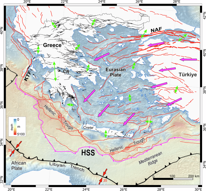
Map summarising the geotectonic setting of Greece and indicating the main tectonic features and kinematics23,45,47. Faults in onshore Greece are active traces from this study. Faults offshore Greece and onshore neighbouring countries are summarized from citations23,45,49,64. Purple arrows indicate average horizontal GNSS velocities with respect to stable Eurasia while green indicate extension directions47. Red arrows represent the orientation of the plate-convergence while numbers the relative rate. HSS = Hellenic Subduction System, KFS = Kefalonia Fault System, NAF = North Anatolian Fault, CR = Corinth Rift.Offshore digital elevation model is from EMODnet (https://doi.org/10.12770/ff3aff8a-cff1-44a3-a2c8-1910bf109f85).
In an effort to identify chronological markers and establish relative chronology of faulting on the landscape of Greece, some workers have used rupture younger than the last glacial maximum (LGM = ~18 thousand years) in separating “faults with post-glacial activity” from older faults. This concept, originally proposed in Greece by Armijo et al.46, reflects the conceptual initiation of a period of landscape stability (post-LGM) following elevated climate-induced landscape instability during the last glacial period, has been tested and used by many studies in Greece and the circa-Mediterranean subsequently (i.e.35,37,50,51,52,53,54,55,56). In parts of Greece, such as Crete and the Peloponnese, these “post-glacial traces” in limestone substrates are represented by clearly mappable elongate ribbons of bedrock exposure, visible as pale, bare or poorly vegetated scarps traversing the landscape.
As a mountainous country with varying basement lithologies there are, however, many parts of the Greek landscape that lack youthful chronological markers. Much of the country has been terrestrial for at least the last 5 million years and thick sequences (>2 km) of alluvial and/or terrestrial deposits are present in many places. Fault-traces restricted to mountainous areas are commonly preserved only as lineaments in the landscape (i.e. topographic fault-scarps) and/or as fault damage zones in bedrock. The longevity of a fault-scarp or fault-line scarp in bedrock depends on the resistance to erosion of the rock itself, as well as the local erosional regime28. In some lithologies and erosional circumstances, fault traces may last for hundreds of thousands of years, while in others they will disappear within decades to hundreds of years. Furthermore, the expression of an old inactive fault in the landscape may be exaggerated by differential erosion where contrasting lithologies are present on either side. To better understand the persistence of fault scarps in varying materials and our ability to detect them using available data, we assessed the geomorphic expression of the fault traces associated with each historical surface-rupturing earthquake in Greece. In many cases, we found that surface ruptures recorded in the literature for large earthquakes in the last 2500 years are difficult to identify in the available DEMs and satellite imagery.
In the absence of comprehensive and accurate, nation-wide, youthful geochronological markers a philosophical decision was required on how inclusive the database should be. The decision influences whether all active or potentially active faults are included within the database, or merely the largest and most obvious active faults. To avoid the possibility of omitting significant seismic sources, we have chosen to be inclusive, and extend the time-window of ‘active faulting’ to include the Quaternary (i.e., since 2.58 Ma). This definition was adopted because faulted Quaternary alluvial fans, that retain their original fan morphology, and lowland basins provide widespread chronostratigraphic markers in Greece (note that although these alluvial fans are considered Quaternary in age, most likely they are considerably younger). In AFG, fault-traces displacing these fans are designated as ‘active’ (Fig. 5a). Fans adjacent to lowland basins commonly exhibit gently undulating surface morphology and likely represent areas of late Quaternary deposition (probably < 70,000 years, the start of the last glacial period of landscape modification). Where these surfaces are displaced by faults, there is little doubt that they should be regarded as ‘active’, even using the commonly accepted criterion of 125,000 years. Lowland basins are normally sites of deposition, so existing surfaces are necessarily young (in many cases they are inferred to be Holocene in age). Fault traces preserved across these surfaces are considered “active”, while many traces buried by ongoing deposition may also be “active”. Our geomorphological mapping is unable to locate these concealed active faults, although in some cases their existence can be inferred by along-strike projection of fault traces into the basin. Further, all traces characterized as ‘sharp’ (see following section) are potential indicators for late-Pleistocene and/or Holocene activity and should also be considered as “active”.
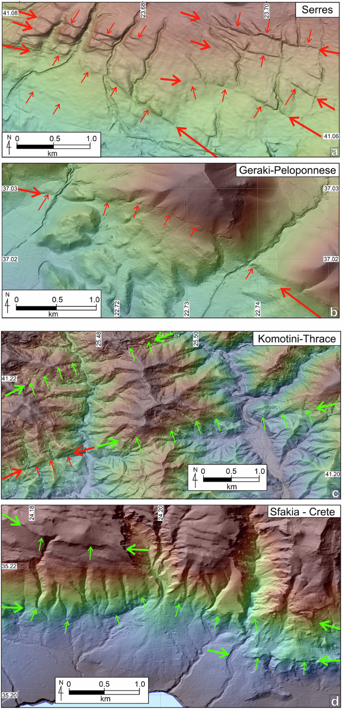
Examples of “active” and “probably active” fault traces in the landscape. (a) Multiple sharp active traces of the Serres Fault crossing a Quaternary fan in the Serres area (2.5 km NE from Chryso). Note that fault traces displace fans, that retain their depositional morphology. (b) The West Parnon Fault displaces youthful alluvial deposits where it crosses two small streams 4 km NE of Geraki in the central Peloponnese. Active faults in (a) and (b) are marked close to the edge of the figure with heavy red arrows; traces are indicated using lighter arrows at right angles along their length. (c) The Kavala-Xanthi-Komotini Fault System in Thrace (northeast Greece), includes active and probably active fault traces. The western trace in this image, about 14 km northeast of Komotini, has a sharp geomorphic expression and is clearly active; its northeast extension lacks this character, nevertheless, facetted spurs, an abrupt change in land elevation and river entrenchment strongly indicate the presence of a fault. Another trace of similar strike about 1.8 km to the north, is also attributed as probably active. (d) Traces of the Sfakia-Sella Fault System in southwest Crete (Sfakia region) features prominent triangular facets and a clear topographic signature without, however, a clear continuous active trace with identifiable postglacial scarps. The coordinate system used is WGS 84, EPSG: 4326.
Thus, within the AFG active faults are those that have ruptured the surface during the Quaternary, leaving remnants of geomorphic expression (note that some may not qualify as “active” using strict application of definitions described above). These faults warrant further investigation (e.g., constrain the timing of their last rupture and/or their paleoearthquake history, earthquake recurrence interval, earthquake magnitude, etc) to better understand the hazard they represent. For the purposes of seismic hazard assessment, in the interests of inclusivity, named faults that have active fault traces should be regarded as active unless otherwise proven. Of the 892 faults in the database, 54% have active traces and thus should be regarded as active as defined within this database; the other 46% may be optionally treated differently within the seismic hazard assessment, or excluded from the assessment altogether.
A classification of fault activity in AFG
Assigning fault activity involved checking for scarps across Quaternary deposits, or for facets on bedrock spurs, where lineaments are present at the margin of basinal deposits. Here, where either a scarp in Quaternary sediments or fault facets were identified, the fault was described as “active”. Where younger materials are not displaced, a trace may be defined as “active” when: a) it is located directly along-strike from a demonstrably active trace; b) there is a clear structural connection with demonstrably active traces; and/or c) when there is a clearly ‘sharp’ trace (i.e., earthquake fault-scarp) identified somewhere along its length (Fig. 5a). Fault traces that do not displace young sediments, do not meet the above criteria or whose extent is limited to land underlain by bedrock, are characterised as “probably active” (Fig. 5b). Future investigation of individual fault traces designated as “probably active” in our dataset may change their attribution to “active” (or vice versa). Fault traces that we attribute as “uncertain” represent features that do not meet any of the above criteria and, further, there is uncertainty whether they represent stratigraphy and not faulting (i.e., represent an erosional expression of contrasting lithologies) or whether they are relict older faults or folds that are no longer active. While there is no intention to include inactive faults in the AFG, it remains possible that the dataset contains some of these older faults.
A geomorphic classification of active fault traces
To assign confidence level on our fault trace mapping, we have introduced a qualitative geomorphic trace descriptor. This geomorphic classification was only undertaken for faults attributed “active” or “historically active” (the latter where discernible). Where historically active traces are not resolvable, they are attributed as “not applicable” (na). We have assigned to active and historically active faults the primarily qualitative geomorphic descriptor of “sharp”, “moderate”, “rounded” or “poor” to reflect geomorphic expression in the landscape. The “sharpness” of expression of fault traces in natural situations is a continuum and the qualitative descriptors are necessarily imprecise, with overlap between these terms. Examples of each geomorphic descriptor are illustrated in Fig. 6. Where a trace is “sharp” anywhere along its length, the entire trace is considered “sharp”. The same rule is applied to other options in this field (i.e., in the progressive sequence from “sharp”, “moderate”, “rounded” to “poor”). In terms of its use as an indicator for accuracy of line location, we estimate that “sharp” and “moderate” traces are located within 100 metres of the fault itself. “Rounded” and “poor” traces have a less certain location, which we estimate to range from 100 to 1000 meters. Further, some inference for timing of rupture may be gained from the geomorphic expression of fault traces. The classifications provided may be used as qualitative estimates for the timing of the last rupture. Faults attributed as “sharp” may be interpreted as having ruptured within the Holocene, for example, while those with “rounded” attribution probably last ruptured substantially earlier (e.g., 100 kyr to 1 Myr ago). Although clearly, a “sharp” scarp will remain longer in the landscape on competent erosion-resistant rocks than in soft sediments, a qualitative use of this geomorphic descriptor field may help identify sites suitable for future paleoseismological studies. In summary, these descriptors can be viewed as indicators of the ‘confidence level’ with which each trace is represented on the landscape.
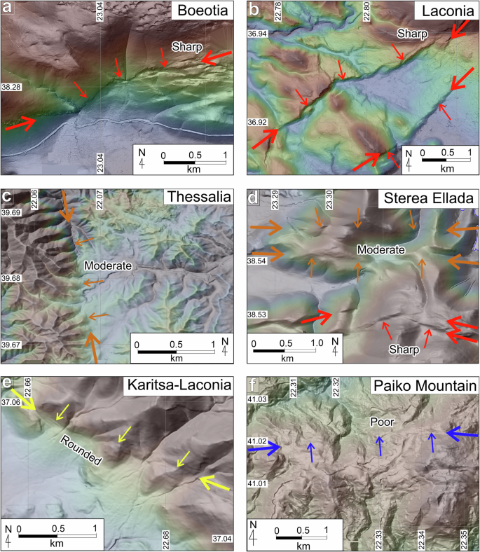
Examples of varying geomorphic expressions of active faults. Maps illustrate typical examples of “sharp” (a,b), “moderate” (c,d), “rounded” (e) and “poor” (f) traces of active faults in AFG. Heavy arrows along the strike of traces identify the fault, while lighter arrows at right angles mark the location of the fault trace. Arrows are colour-coded according to the geomorphic expression of the trace (red = sharp, orange = moderate, yellow = rounded, blue = poor). (a) Traces of the Neochori-Leontari Fault about 5.5 km southwest of Neochori (Boeotia Prefecture) with a sharp geomorphic expression on the landscape; (b) Active traces of the Apidea Fault System in Lakonia (Eastern Peloponnese) sharply displace Quaternary fans and streams; (c) trace of the Farkadona-Kalyvia Fault System approx. 1.6 km southwest of Megalo Eleftherochori in Thessalia traverse dissected hill country, exhibiting facetted spurs but a rounded geomorphic expression; (d) Traces of the active Lokris and northern Orchomenos fault systems in central Greece (Sterea Ellada), displacing ridge-crests that have “moderate” geomorphic expressions (orange arrows), while the traces of the southern Orchomenos Fault are markedly clearer and are characterised as “sharp” (red arrows); (e) The active trace with “rounded” geomorphic expression of the Karitsa Fault System in south Peloponnese (Laconia – 5.4 km northeast of Agioi Anargyri). The fault traces displace ridge systems and active fans, and bound entrenched streams; (f) The “poor” geomorphic expression of the Belles Fault System in Paiko Mountain Range in Macedonia: although its traces appear to clearly displace a series of ridges, its landscape expression is limited and difficult to locate between displaced features. Coordinate system: WGS 84, EPSG: 4326.
To complement the geomorphic analysis, we have also assessed whether fault traces exert control on local sediment deposition (depositional control – DC) (Tables 1, 2; Fig. 1). Where a trace defines a range-front between hill/mountain and Quaternary depocenters or shows indications of Holocene depositional control (interpreted as likely to be an association between fault development and deposition), it is attributed as DC (Fig. 1). As we have done for the sharpness descriptor, any fault-trace with evidence indicating DC anywhere along its length, is attributed DC in its entirety. On the other hand, where there is either no recent deposition along the length of the fault trace or no unequivocal indication of fault-controlled deposition the trace is characterised as ‘na’ = ‘not applicable’ (Table 2).
A geomorphological caution – Landscape modification
The long human occupation of Greece (>5000 yrs) has implications for active fault preservation. Significant historic (<1500 years) and pre-historic (1500 to 5000 years BP) anthropic landscape modification is recorded in many parts of Greece57,58. Such modification has changed the original surface expression of faults, particularly of lowland faults (in intensively cultivated areas), across much of the country. Because active fault ruptures are commonly small in displacement, they are particularly prone to anthropic modification. The impacts of anthropic modification include soil development and soil loss leading to degradation of fault scarps on flat or gently sloping landscapes, terrace-building and other constructions that disguise the presence of faults, and consequent blurring or obliteration of geomorphology useful in defining faults as ‘active’. Local studies, mostly for the purposes of archaeology57,58, provide a local basis for understanding the impact and chronology for potential soil development and thus fault scarp modification.